Phot 2 conc
This mode allows for mapping the concentration of fluorescent molecules using single-molecule FLIM imaging data. The script requires the .pkl files created in the EXTRACT from PTU and FILTER mode. Important! This script does not read the .ptu files directly. It is necessary to use the EXTRACT from PTU and FILTER mode first!
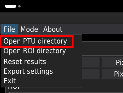
Open the data directory
To open the folder containing the files for analysis, select Open PRU directory from the File menu.
Note. The folder should contain only .ptu files and the corresponding .pkl and .png files.
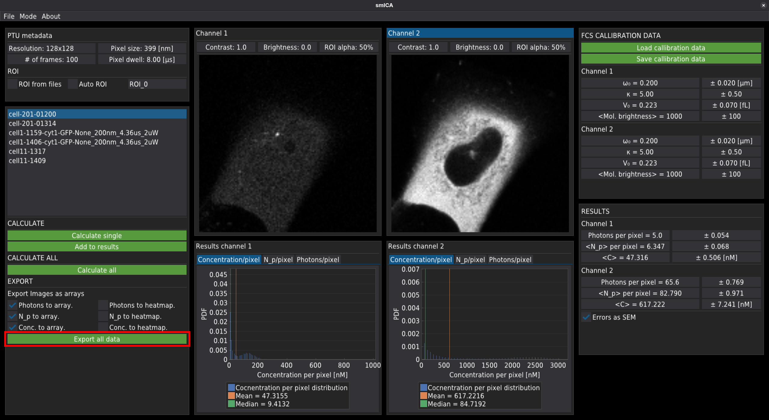
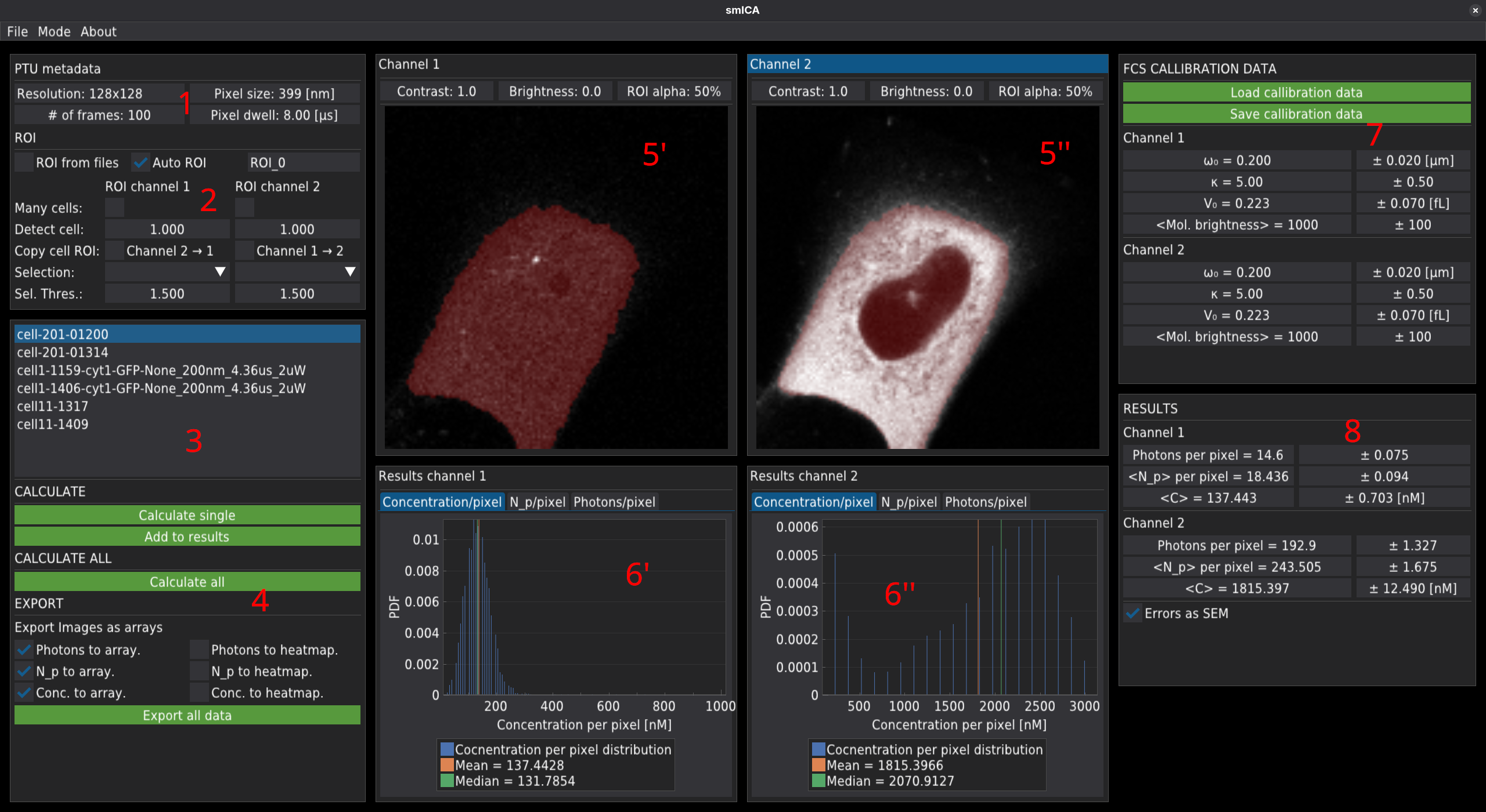
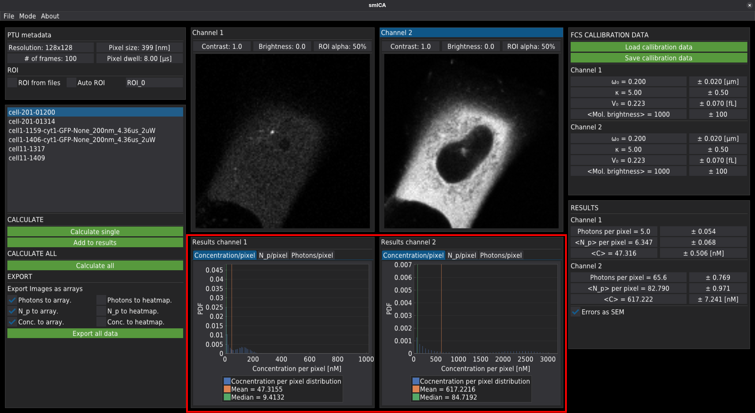
The main window
The GUI is divided into several sections.
PTU metadata containing the information about image acquisition.
ROI containing the selection panel for choosing the method for the region of interest. It also allows control of the automatic ROI see below.
The list of files for analysis that are located in the PTU folder.
Buttons starting the calculations and export options.
Analysed image - 5’ for channel 1 and 5’’ for channel 2.
Histograms of the concentration number of molecules or number of photons per pixel - 6’ for channel 1 and 6’’ for channel 2.
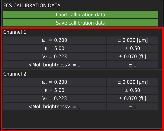
The FCS calibration data
Mean results.
Calibration data
Loading calibration
It is recommended to load or input the FCS calibration data and molecular brightness of the fluorophore, right after loading the PTU directory. Calibration data is obligatory for the proper calculation of the number of molecules and concentration. The calibration data can be loaded from the JSON files (exemplary files are stored in the samples folder on the repository site).
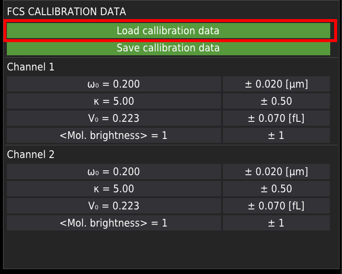
Manual input
Alternatively, the calibration data can be entered manually by entering the correct values in the corresponding fields shown below.
Saving calibration data
The manually entered calibration values can be saved by pressing the Save calibration data button.
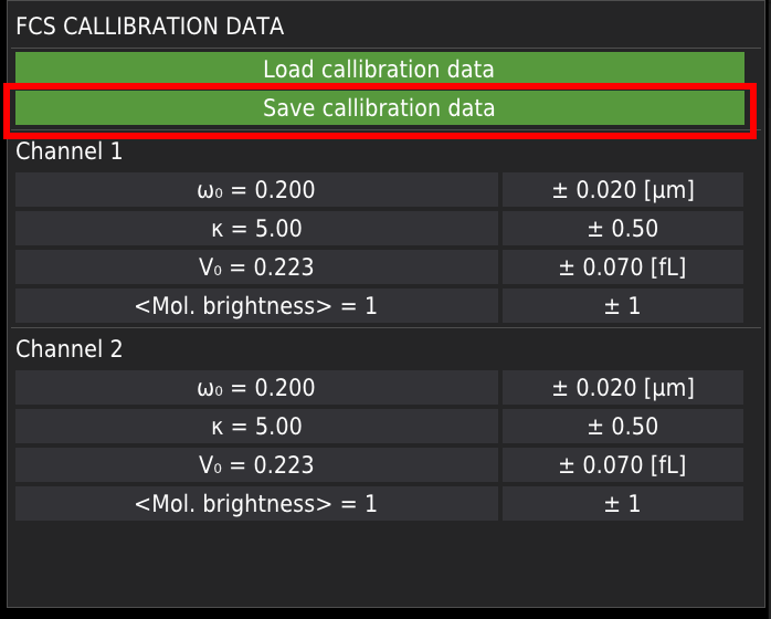
Image analysis
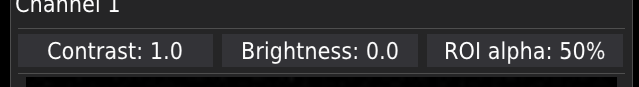
Displaying the images
The analysed image is displayed in windows corresponding to channel 1, 2 or both. Above the images, the user can adjust the visibility of the images by changing contrast and brightness, or the overlaying ROI’s alpha channel; see ROI section.
Note, the adjustment is applied only to the displayed image (channel 1 or channel 2) and does not affect the results.
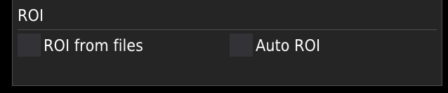
The region of interest
The region of interest, ROI, is a part of the image that will be considered during the image analysis. It is marked in red on the image. The software has two options for ROI definition: ROI from files or Auto ROI.
ROI from files
This option requires externally created roi files. Examples of externally generated ROI files (generated with ImageJ) are in the samples folder on the repository site. Before import, the externally created ROI files should be rewritten to a format readable by the smICA software with the REWRITE ROI tool.
Note that
The ROI file for each channel is created separately.
The filename of the ROI file should have the same structure as the PTU file with an additional string at the end of the filename, according to the example given below.
file_name.ptu
file_name_roi0_ch_1.dat - (ROI file for channel 1)
file_name_roi0_ch_2.dat - (ROI file for channel 2)
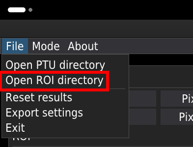
The ROI files will load automatically for the given .ptu file. To import the ROI files, the user must specify the folder containing the files by selecting the path using the Open ROI directory option from the File menu. It is possible to have many ROI files per .ptu file. The multiple ROI files are identified by numeration in the roiX part of the ROI’s file name, where X denotes the number of the ROI file.
Auto ROI
Selecting the Auto ROI checkbox displays the ROI control panel for both channels, and the ROI on the image as a red field.
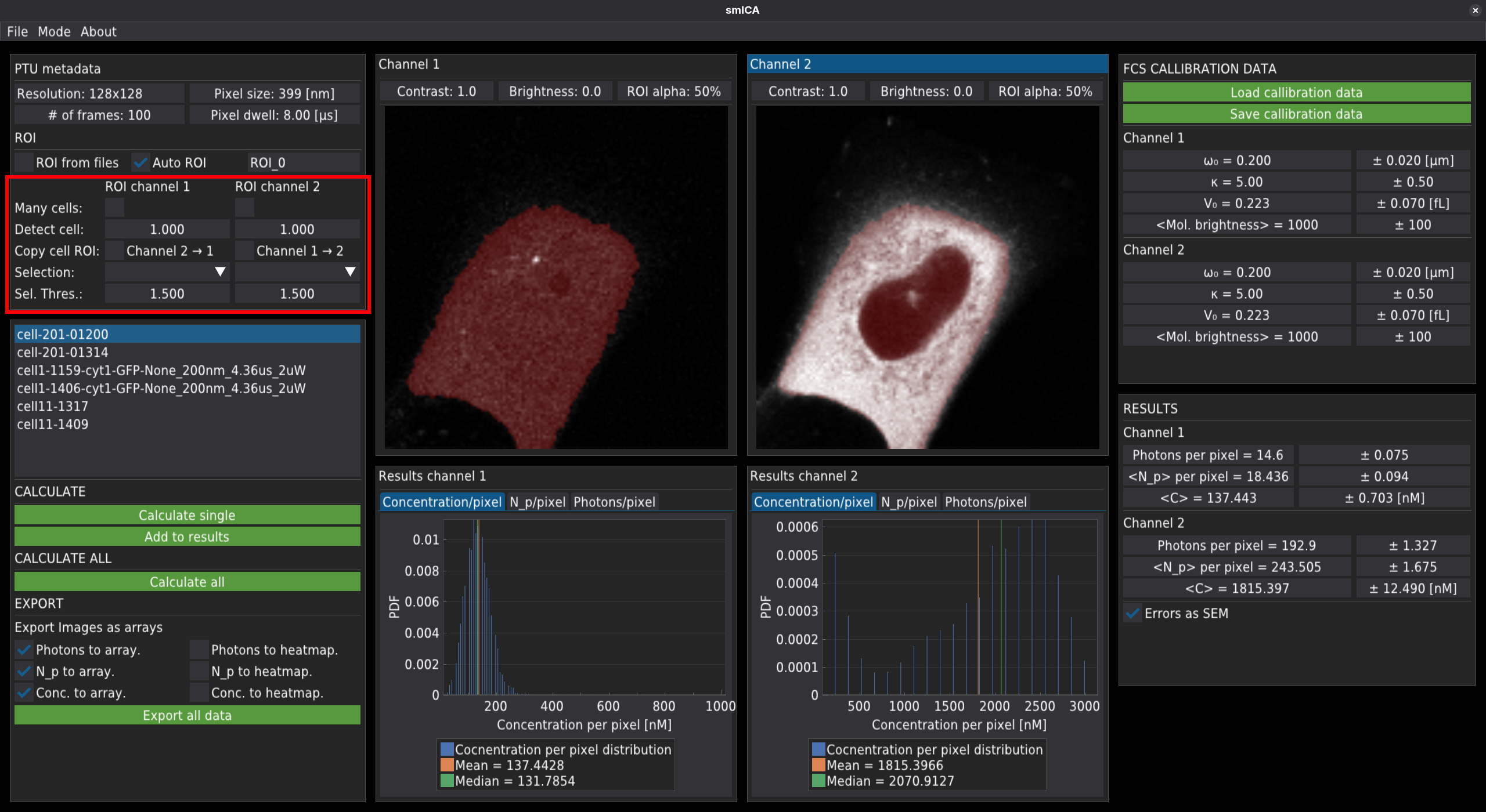
Currently, the automatic ROI option offers:
automatic detection of a single cell,
automatic detection of more than one cell and selection of the ROI of interest (clicking on the image),
copying ROI between channels,
finding dark or bright areas,
subtracting dark or bright areas,
finding and subtracting many bright spots.
All modes use the OTSU thresholding method. The user can independently adjust the original OTSU threshold by changing the corresponding sliders in each channel.
ROI copying between channels is performed only in the “detect cell” mode. Note that when the checkbox is selected, the thresholding levels can be regulated only in the original channel. For example, selecting “Channel 1->2” will copy the ROI from channel 1 to channel 2.
The ROI generated in auto-mode will be stored as ROI files and can be reused if necessary. For this purpose, within the folder containing the analysed .ptu files, a new ROI folder will be created.
Calculate the results
To correctly calculate concentration maps, the user must provide or import calibration data obtained from FCS measurements, including the focal volume width , the structure parameter , and the mean molecular brightness.
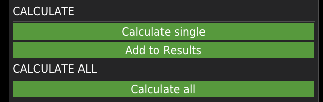
Pressing the Calculate single button calculates and displays results for a single file. Press the Add to results button to save the results and retain the Auto ROI settings for the current file. The calculate all button will automatically calculate and store the data for all files, one by one.
The mean result will be displayed in tables within the RESULTS window on the right-hand side of the screen
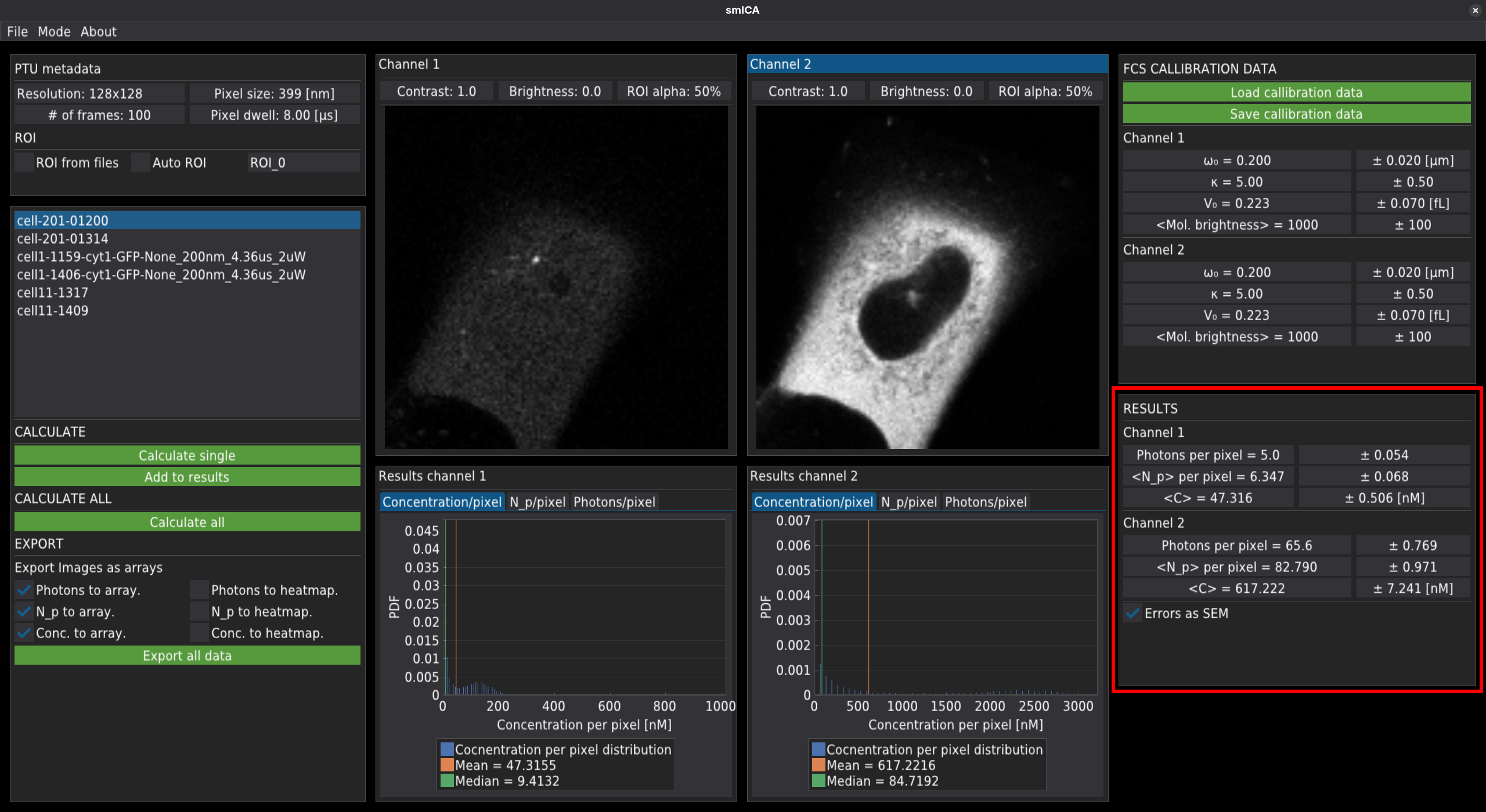
and presented in the form of per-pixel distributions for concentration, number of molecules - N_p, or number of photons, respectively.
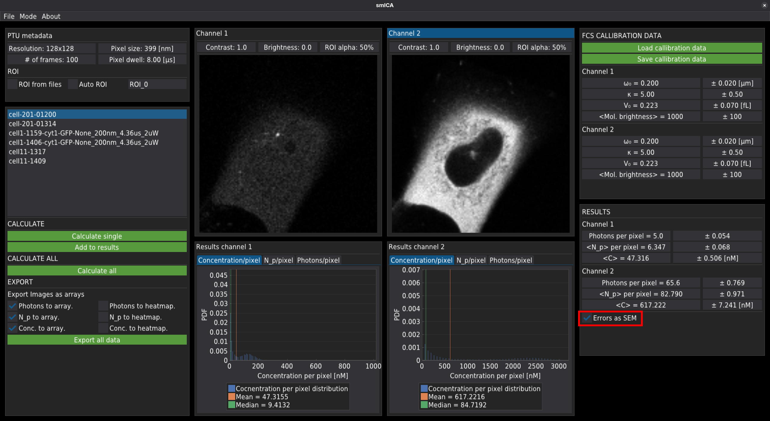
The error values displayed in the RESULTS window can be calculated in two ways. The checkbox Errors as SEM switches between them:
In the first case (unmarked checkbox), the error is returned as the mean of the maximum errors calculated for each pixel. Those errors include errors for and the molecular brightness.
The second method for calculation of errors (marked checkbox) returns the standard error of the mean, calculated as the standard deviation over all pixels, divided by the square root of the number of pixels within the ROI or image (depending on whether the ROI is used or not).
Export results
During calculation, the data will be automatically exported according to the rules marked in the export panel.
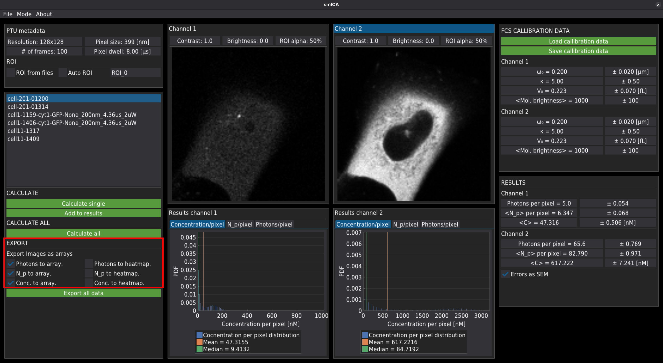
The to array means that the script will create a .csv file containing the array (size of the image) containing a number of photons, molecules, or concentration in a given pixel.
“to heatmap” means that the heatmap will be exported as the .png file.
To export the averaged data as a table, press the “Export all data” button.